Automatic sliding gate controller circuit Simple gate open/close controller circuit Not gate circuit diagram and working explanation
Simple Gate Open/Close Controller Circuit
Gate not circuit diagram input power through explanation working button circuitdiagram connected then Gate sliding automatic controller circuit diagram wiring door gates sensor close motion delay circuits reverse closing before system open using [pdf] fundamentals of mosfet and igbt gate driver circuits
14+ xnor gate circuit diagram
4011 nand circuit pinout datasheet integrated basic circuitsGate igbt mosfet driver circuits fundamentals figure Gate xnor cmosedu nand xorDigital lab.
Proposed gate driver circuit: (a) schematic of a single stage; (bNot circuit gate inverter logic diagram schematic gates diodes practical resistors bipolar composed exclusively transistors operation Circuito remote push abrir circuits opener axtudo controladorThe not gate.


Digital Lab - Basic 2-Input NAND Gate Circuit | Digital IC Projects
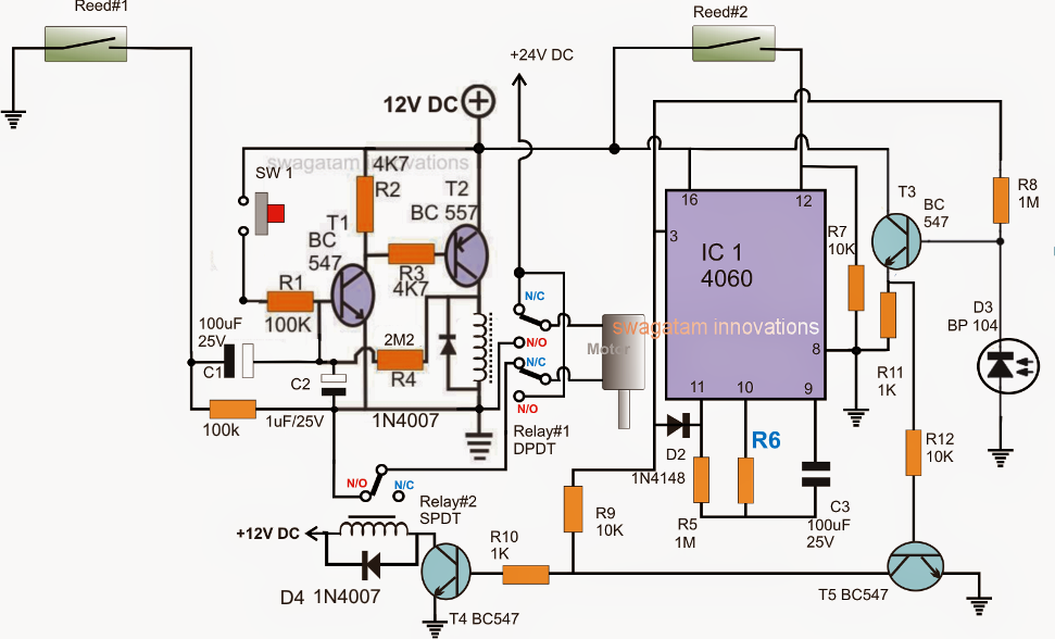
Automatic Sliding Gate Controller Circuit
![[PDF] Fundamentals of MOSFET and IGBT Gate Driver Circuits | Semantic](https://i2.wp.com/d3i71xaburhd42.cloudfront.net/8e71744b92ac83f0fba043fc41a41c43ee9e55fa/6-Figure2-1.png)
[PDF] Fundamentals of MOSFET and IGBT Gate Driver Circuits | Semantic

NOT Gate Circuit Diagram and Working Explanation

Simple Gate Open/Close Controller Circuit

14+ Xnor Gate Circuit Diagram | Robhosking Diagram

Proposed gate driver circuit: (a) Schematic of a single stage; (b
